Degital Technology

    Get Free Digital Marketing information and much more.
  • Home
  • About
  • 5G Mobile
  • CDMA Mobile
  • CONTACT
  • PRIVACY

Monday, 1 January 2018

International Mobile Station Identity (IMSI)

Mobile stations are identified by the identity of the international mobile station Identity (IMSI). The IMSI consists of up to 10 to 15 numeric digits. The first three digits of the IMSI are the country code of the mobile (MCC), the remaining digits are the National NMSI mobile station identity. The NMSI consists of the mobile network code (MNC) and the mobile station identification number (SIDS).
MCCMSNMSIN
NMSI
IMSI ≤15 digits
  • MCC: Mobile Country Code
  • MNC: Mobile Network Code
  • MSIN: Mobile Station Identification
  • NMSI: National Mobile Station Identity
An IMSI that is 15 digits in length is called a class 0 IMSI (NMSI is the 12 digits in length). IMSI, which is less than 15 digits in length, is called a class 1 IMSI (NMSI the length is less than 12 counts). For CDMA operation, the same IMSI may be registered in multiple mobile stations. Individual systems may or may not allow these capabilities. The management of these functions is a function of the base station and the system operator.

CDMA - Techniques

Rake Receiver

Due to the reflection on the challenges of a broadband, radio channel can consists of many copies (multipath), signals originally transmitted with different amplitude, phase, and delay. If the signal components arrive over a chip period of each other, a rake receiver may be used to adjust and combine. The Rake receiver uses a principle of diversity through multiple paths. The figure given below shows the Rake receiver scheme.
Rake Receiver
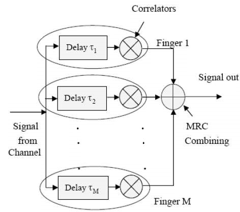
The Rake receiver processes several multipath signals components. The correlator outputs are combined to achieve better reliability and communication performance. Bit decision on the basis of a single correlation can produce a large bit error rate as multipath component processed by the fact that the correlator can be damaged by discoloration. If the output of a correlator is corrupted by fading, the other cannot be, and the corrupt signal can be reduced by the weighting process.

Walsh Code

Walsh Codes are most commonly used in the orthogonal codes of CDMA applications. These codes correspond to lines of a special square matrix called the Hadamard matrix. For a set of Walsh codes of length N, it consists of n lines to form a square matrix of n × n Walsh code.
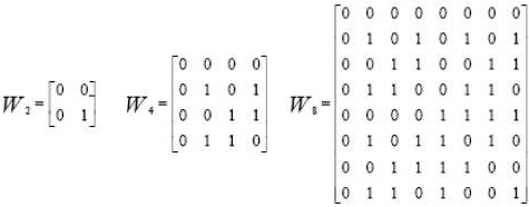
The IS-95 system uses 64 Walsh function matrix 64. The first line of this matrix contains a string of all zeros with each of the following lines containing different combinations of bit 0 and 1. Each line is orthogonal and equal representation for binary bits. When implemented with the CDMA system, each mobile user uses one of the 64 sequences of rows in the matrix as a spreading code. And, it provides zero cross-correlation among all the other users. This matrix is defined recursively as follows −
Walsh Matrix Code
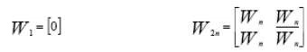
Where n is a power of 2 and indicates the different dimensions of the matrix W. Further, n represents the logic NOT operation on all bits in this matrix. The three matrices W2, W4, and W8, respectively show the Walsh function for the dimension 2, 4, and 8.
Walsh Functions
Each line of the 64 Walsh matrix 64 corresponds to a channel number. The channel number 0 is mapped to the first row of the Walsh matrix, which is the code of all zeros. This channel is also known as the pilot channel and is used to form and to estimate the impulse response of a mobile radio channel.
To calculate the cross-correlation between the sequences, we will need to convert the bits into the matrix to form the antithesis of ± 1 values. However, all users on the same CDMA channel can be synchronized with an accuracy of one chip interval using a common long PN sequence. It also functions as a data scrambler.
  • Walsh Code is a group of spreading codes having good autocorrelation properties and poor cross correlation properties. Walsh codes are the backbone of CDMA systems and are used to develop the individual channels in CDMA.
  • For IS-95, there are 64 codes available.
    • Code `0’ is used as the pilot and code `32’ is used for synchronization.
    • Codes 1 through 7 are used for control channels, and the remaining codes are available for traffic channels. Codes 2 to 7 are also available for traffic channels if they are not needed.
  • For cdma2000, multitude of Walsh codes exist, which vary in length to accommodate the different data rates and Spreading Factors of the different Radio Configurations.
  • One of the 64 orthogonal bit pattern at a rate of 1.2288 Mcps.
  • Walsh codes are used to identify the data for each individual transmission. In the forward link, they define forward code channels within a CDMA frequency.
  • In the reverse link, all 64 codes are used by each reverse channel to carry information.
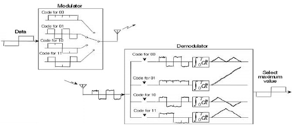
Take a look at the following illustration. It shows how multiplexing is carried out using Walsh Code.
Multiplexing Using Walsh Code

Read More
  • Share This:  
  •  Facebook
  •  Twitter
  •  Google+
  •  Stumble
  •  Digg

CDMA Capacity

The factors deciding the CDMA capacity are −
  • Processing Gain
  • Signal to Noise Ratio
  • Voice Activity Factor
  • Frequency Reuse Efficiency
Capacity in CDMA is soft, CDMA has all users on each frequency and users are separated by code. This means, CDMA operates in the presence of noise and interference.
In addition, neighboring cells use the same frequencies, which means no re-use. So, CDMA capacity calculations should be very simple. No code channel in a cell, multiplied by no cell. But it is not that simple. Although not available code channels are 64, it may not be possible to use a single time, since the CDMA frequency is the same.

Centralized Methods

  • The band used in CDMA is 824 MHz to 894 MHz (50 MHz + 20 MHz separation).
  • Frequency channel is divided into code channels.
  • 1.25 MHz of FDMA channel is divided into 64 code channels.

Processing Gain

CDMA is a spread spectrum technique. Each data bit is spread by a code sequence. This means, energy per bit is also increased. This means that we get a gain of this.
P (gain) = 10log (W/R)
W is Spread Rate
R is Data Rate
For CDMA P (gain) = 10 log (1228800/9600) = 21dB
This is a gain factor and the actual data propagation rate. On an average, a typical transmission condition requires a signal to the noise ratio of 7 dB for the adequate quality of voice.
Translated into a ratio, signal must be five times stronger than noise.
Actual processing gain = P (gain) - SNR
= 21 – 7 = 14dB
CDMA uses variable rate coder
The Voice Activity Factor of 0.4 is considered = -4dB.
Hence, CDMA has 100% frequency reuse. Use of same frequency in surrounding cells causes some additional interference.
In CDMA frequency, reuse efficiency is 0.67 (70% eff.) = -1.73dB

Advantages of CDMA

CDMA has a soft capacity. The greater the number of codes, the more the number of users. It has the following advantages −
  • CDMA requires a tight power control, as it suffers from near-far effect. In other words, a user near the base station transmitting with the same power will drown the signal latter. All signals must have more or less equal power at the receiver
  • Rake receivers can be used to improve signal reception. Delayed versions of time (a chip or later) of the signal (multipath signals) can be collected and used to make decisions at the bit level.
  • Flexible transfer may be used. Mobile base stations can switch without changing operator. Two base stations receive mobile signal and the mobile receives signals from the two base stations.
  • Transmission Burst − reduces interference.

Disadvantages of CDMA

The disadvantages of using CDMA are as follows −
  • The code length must be carefully selected. A large code length can induce delay or may cause interference.
  • Time synchronization is required.
  • Gradual transfer increases the use of radio resources and may reduce capacity.
  • As the sum of the power received and transmitted from a base station needs constant tight power control. This can result in several handovers.
CDMA Disadvantages

CDMA - Network

CDMA Network is the system meant to regulate CDMA technology. It includes all aspects and functionality starting from the base station, transmitting antenna, receiving antenna, to mobile switching centers.

CDMA Network Overview

A base station is an essential element of the CDMA network. A base station covers a small geographical area called a cell. A cell may be omnidirectional or sectoral. Each base station has a transmitting antenna and two receiving antennas for each cell. Two receiving antennas are used per cell for the purpose of spatial diversity. In many applications, it is a BSC (Base Station Controller), which controls several base stations.
As the rate of the mobile phone data is either 13kbps or 8kbps, which is nonISDN, but the switches which are the mobile switching center (MSC) are generally switched to 64 kbps. Therefore, before it is switched, it is necessary to convert this mobile data rates to 64 kbps. This is accomplished by a member, which is the transcoder. The transcoder may be a separate element or it can be collocated in each base station or MSC.
All base stations are connected to the MSC, which is the mobile switchingcenter. MSC is the entity that manages the establishment, connection, maintenance, and disposal of calls within the network and also with the outside world.
MSC also has a database called HLR/AC, which is a home location register/authentication center. HLR is the database, which maintains the database of all network subscribers. AC Authentication Centre is the part of the security of the HLR, which some algorithms to examine mobile phones.
The MSC is connected to the outside world, i.e. the fixed line network. MSC can also be connected to several other MSCs.

CDMA Identities

Network Identities −
  • SID (System Identity)
  • NID (Network Identity)
Mobile Station Identities −
  • ESN (Electronic Serial Number)
  • Permuted ESN
  • IMSI (International Mobile Station Identity)
  • IMSI_S
  • IMSI_11_12
  • Station Class Mark

System and Network Identity

A base station is a member of a cellular system and a network. A network is a subset of a system. The systems are installed with an identification calledIdentification System (CIS). The networks with a system receiving isNetwork identification (NID). It is a uniquely identified network pair of (SID, NID). The mobile station has a list of one or more home (non-roaming) pairs (SID, NID).

SID

A system identification indicator 15 bits (SID) is stored in a mobile station. It is used to determine the host system of the mobile stations. The bit allocation of the system identification indicator is shown below.
SID
The distribution of international codes (INTL) (bits 14 and 13) is also shown in the table. Bits 12-0 is assigned to each US system by the FCC for non-US countries. The bit allocation will be made by local regulatory authorities.

NID

NID has a range of 0-65535 reserved values. Value of 65535 in a SID means, NID pair is to indicate that the Mobile Station considers the entire SID as home.
NID

Systems and Networks

A mobile station has a list of one or more home (non-roaming) pairs (SID, NID). A mobile station is roaming when the base station broadcast (SID, NID) pair does not match with one of the non-roaming mobile stations (SID, NID) pairs.
A mobile station is a foreign NID roamer −
  • if the mobile station is roaming and there are some (SID, NID) pair in the mobile stations (SID, NID) list that corresponds to SID.
  • if the mobile station is roaming and there are some (SID, NID) pair in the mobile stations (SID, NID) list for which no matching SID is available (means a mobile station has roaming customer foreign SID).

Electronic Serial Number (ESN)

ESN is a 32-bit binary number that uniquely identifies the mobile station in a CDMA cellular system. It should be set at the factory and cannot be easily changed in the field. Changing the ESN will require special equipment, not normally available to subscribers. The bit allocation of ESN is shown below −
ESN
The circuit that provides the ESN must be isolated so that no one can contact and tamper. Attempts to change the ESN circuit should make the mobile station inoperative. At the time of the issuance of the initial acceptance, the manufacturer must be assigned a code Manufacturers (MFR) in the eight most significant bits (bits 31-24 bits) 32-bit serial number. Bits 23-18 are reserved (initially zero). And, every manufacturer only allocates 17 bits to 0. When a manufacturer has used almost all possible combinations of serial numbers in bits 17-0, the manufacturer may submit a notification to the FCC. The FCC will assign the next sequential binary number in the reserve block (bits 23 through).

Permuted ESN

CDMA is a spread spectrum technique where multiple users to access the system at the same example in a cell, and of course on the same frequency. Therefore, it discriminates the users on the reverse link (i.e. information from MS to the base station). It spreads information using codes that are unique to the mobile station in all the CDMA cellular systems. This code has an element that is the ESN, but it doesn’t use the ESN in the same format instead, it uses an ESN swapped.
If there are two mobiles in a cell of the same brand and have consecutive serial numbers and for the receiver of the base station, it becomes difficult to connect them. Therefore, to avoid a strong correlation between the long codes corresponding to successive ESN, we use permuted ESNs.
Read More
  • Share This:  
  •  Facebook
  •  Twitter
  •  Google+
  •  Stumble
  •  Digg

TDMA - Technology

Time Division Multiple Access (TDMA) is a digital cellular telephone communication technology. It facilitates many users to share the same frequency without interference. Its technology divides a signal into different timeslots, and increases the data carrying capacity.

TDMA Overview

Time Division Multiple Access (TDMA) is a complex technology, because it requires an accurate synchronization between the transmitter and the receiver. TDMA is used in digital mobile radio systems. The individual mobile stations cyclically assign a frequency for the exclusive use of a time interval.
In most of the cases, the entire system bandwidth for an interval of time is not assigned to a station. However, the frequency of the system is divided into sub-bands, and TDMA is used for the multiple access in each sub-band. Sub-bands are known as carrier frequencies. The mobile system that uses this technique is referred as the multi-carrier systems.
In the following example, the frequency band has been shared by three users. Each user is assigned definite timeslots to send and receive data. In this example, user ‘B’ sends after user ‘A,’ and user ‘C’ sends thereafter. In this way, the peak power becomes a problem and larger by the burst communication.
TDMA

FDMA and TDMA

This is a multi-carrier TDMA system. A 25 MHz frequency range holds 124 single chains (carrier frequencies 200) bandwidth of each kHz; each of these frequency channels contains 8 TDMA conversation channels. Thus, the sequence of timeslots and frequencies assigned to a mobile station is the physical channels of a TDMA system. In each timeslot, the mobile station transmits a data packet.
The period of time assigned to a timeslot for a mobile station also determines the number of TDMA channels on a carrier frequency. The period of timeslots are combined in a so-called TDMA frame. TDMA signal transmitted on a carrier frequency usually requires more bandwidth than FDMA signal. Due to the use of multiple times, the gross data rate should be even higher.

Advantages of TDMA

Here is a list of few notable advantages of TDMA −
  • Permits flexible rates (i.e. several slots can be assigned to a user, for example, each time interval translates 32Kbps, a user is assigned two 64 Kbps slots per frame).
  • Can withstand gusty or variable bit rate traffic. Number of slots allocated to a user can be changed frame by frame (for example, two slots in the frame 1, three slots in the frame 2, one slot in the frame 3, frame 0 of the notches 4, etc.).
  • No guard band required for the wideband system.
  • No narrowband filter required for the wideband system.

Disadvantages of TDMA

The disadvantages of TDMA are as follow −
  • High data rates of broadband systems require complex equalization.
  • Due to the burst mode, a large number of additional bits are required for synchronization and supervision.
  • Call time is needed in each slot to accommodate time to inaccuracies (due to clock instability).
  • Electronics operating at high bit rates increase energy consumption.
  • Complex signal processing is required to synchronize within short slots.

CDMA - Technology

Code Division Multiple Access (CDMA) is a sort of multiplexing that facilitates various signals to occupy a single transmission channel. It optimizes the use of available bandwidth. The technology is commonly used in ultra-high-frequency (UHF) cellular telephone systems, bands ranging between the 800-MHz and 1.9-GHz.

CDMA Overview

Code Division Multiple Access system is very different from time and frequency multiplexing. In this system, a user has access to the whole bandwidth for the entire duration. The basic principle is that different CDMA codes are used to distinguish among the different users.
Techniques generally used are direct sequence spread spectrum modulation (DS-CDMA), frequency hopping or mixed CDMA detection (JDCDMA). Here, a signal is generated which extends over a wide bandwidth. A code calledspreading code is used to perform this action. Using a group of codes, which are orthogonal to each other, it is possible to select a signal with a given code in the presence of many other signals with different orthogonal codes.

How Does CDMA Work?

CDMA allows up to 61 concurrent users in a 1.2288 MHz channel by processing each voice packet with two PN codes. There are 64 Walsh codes available to differentiate between calls and theoretical limits. Operational limits and quality issues will reduce the maximum number of calls somewhat lower than this value.
In fact, many different "signals" baseband with different spreading codes can be modulated on the same carrier to allow many different users to be supported. Using different orthogonal codes, interference between the signals is minimal. Conversely, when signals are received from several mobile stations, the base station is capable of isolating each as they have different orthogonal spreading codes.
The following figure shows the technicality of the CDMA system. During the propagation, we mixed the signals of all users, but by that you use the same code as the code that was used at the time of sending the receiving side. You can take out only the signal of each user.

Read More
  • Share This:  
  •  Facebook
  •  Twitter
  •  Google+
  •  Stumble
  •  Digg

Frequency Division Duplex

In Frequency Division Duplex (FDD), the forward link frequency is not the same as the reverse link frequency. In each link, signals are continuously transmitted in parallel.
Frequency Division Duplex

Example of FDD System

FDD requires two symmetrical segments of spectrum for the uplink and downlink channels.
In a cell phone with a transmitter and receiver, operating simultaneously in such close proximity, the receiver has to filter as much of the signal from the transmitter as possible. More separation of the spectrum, the most effective filters.
FDD System Example
FDD uses a lot of frequency spectrum, generally twice of the required TDD spectrum. In addition, there must be adequate spectrum separation between transmission and reception of the channels. These bands keep saying − it cannot be used, they are unnecessary. Given the scarcity and cost of the spectrum, they are real disadvantages.

Use of FDD

FDD is widely used in different cellular telephone systems. In some systems, the band 869-894 MHz is used as the downlink (DL) spectrum from the cell site tower to the device. And, the band 824-849 MHz is used as the uplink (UL) spectrum of the handset at the cell site.
FDD also works on a cable where transmit and receive channels are given different parts of the cable spectrum, as in cable TV systems. And, filters are used to keep the channels separate.

Disadvantage of FDD

The drawback of FDD is that it does not allow special techniques like multiple antennas, multiple input-output (MIMO), and beamforming. These technologies are an essential element of the new strategies Long Term Evolution (LTE) 4G cell phone to increase the data rate. It is difficult to make broad enough bandwidth to cover both sets of antenna spectrum. Circuit complex dynamic adjustment is required.

Multiple Access Methods

The radio channel is a communication medium shared by several users in a geographic area. Mobile stations are in competition with one another for the frequency resource to transmit their information flow. Without other measures to control concurrent access of several users, collisions can occur. Since collisions are undesirable for connectionoriented communication such as mobile phones, personal/mobile subscriber stations need to be allocated the dedicated channels on request.
Multiple Access Methods
The mobile communication, sharing wireless resources on all users, must be communicated to identify the user. While identifying the user, it is referred to as "multiple access" (Multiple Access) that is receiving a radio wave of a number of transmitting stations in a receiving station (as shown in the following image).

FDMA - Technology

Frequency Division Multiple Access (FDMA) is one of the most common analogue multiple access methods. The frequency band is divided into channels of equal bandwidth so that each conversation is carried on a different frequency (as shown in the figure below).

FDMA Overview

In FDMA method, guard bands are used between the adjacent signal spectra to minimize crosstalk between the channels. A specific frequency band is given to one person, and it will received by identifying each of the frequency on the receiving end. It is often used in the first generation of analog mobile phone.
FDMA

Advantages of FDMA

As FDMA systems use low bit rates (large symbol time) compared to average delay spread, it offers the following advantages −
  • Reduces the bit rate information and the use of efficient numerical codes increases the capacity.
  • It reduces the cost and lowers the inter symbol interference (ISI)
  • Equalization is not necessary.
  • An FDMA system can be easily implemented. A system can be configured so that the improvements in terms of speech encoder and bit rate reduction may be easily incorporated.
  • Since the transmission is continuous, less number of bits are required for synchronization and framing.

Disadvantages of FDMA

Although FDMA offers several advantages, it has a few drawbacks as well, which are listed below −
  • It does not differ significantly from analog systems; improving the capacity depends on the signal-to-interference reduction, or a signal-to-noise ratio (SNR).
  • The maximum flow rate per channel is fixed and small.
  • Guard bands lead to a waste of capacity.
  • Hardware implies narrowband filters, which cannot be realized in VLSI and therefore increases the cost.
Read More
  • Share This:  
  •  Facebook
  •  Twitter
  •  Google+
  •  Stumble
  •  Digg

CDMA - Multiple Access Methods

The possibility to operate in either FDD or TDD mode is allowed for efficient use of available spectrum according to frequency allocation in different regions.

Frequency Division Duplex

A duplex method whereby the Uplink and the Downlink transmissions use two separate frequency bands −
  • Uplink − 1920 MHz to 1980 MHz
  • Downlink − 2110 MHz to 2170 MHz
  • Bandwidth − Each carrier is located on the center of a 5 MHz wide band

Channel Separation

Nominal value of 5 MHz that can be adjusted.

Channel Raster

200 kHz (center frequency must be a multiple of 200 kHz).

Tx-Rx Frequency Separation

Nominal value of 190 MHz. This value can be either fixed or variable (minimum of 134.8 and maximum of 245.2 MHz).

Channel Number

The carrier frequency is designated by the UTRA Absolute Radio Frequency Channel Number (UARFCN). This number is sent by the network (for the uplink and downlink) on the BCCH logical channel and is defined by Nu = 5 * (Frequency uplink MHz) and ND = 5 * (Frequency downlink MHz).

Time Division Duplex

Time division duplex is a technique by which the Uplink and the Downlink transmissions are carried over the same frequency by using synchronized time intervals. The carrier uses a 5 MHz band, although there is a low chip rate solution under study by the 3GPP (1.28 Mcps). The available frequency bands for TDD will be 1900–1920 MHz and 2010 – 2025 MHz.

Duplex Methods of Radio Links

Duplex Methods Radio Links
In case of Time Division Duplex, the forward link frequency is same as the reverse link frequency. In each link, signals are transmitted continuously in turns − just like a ping-pong game.
Ping-Pong

Example of TDD System

TDD uses a single frequency band for both to transmit and to receive. Further, it shares the band by assigning alternate timeslots for transmitting and receiving operations. The information to be transmitted can be voice, video, or computer data in bit-serial format. Each time interval can be 1 byte long or may be a part of several bytes.
TDD alternates the transmission and reception station data over time. Timeslots can be of variable length. Due to the nature of high-speed data, the communicating parties cannot mean that the transmissions are intermittent. Transmissions that appear as simultaneous are actually competing each other. Digitally converted into analog voice, no one can say that it is not a full duplex.
TDD System Example
In some TDD systems, alternative time intervals are of same duration or having both DL and UL; however, the system does not need to be symmetric 50/50. The system may be asymmetrical as required.
For example, while accessing the Internet, the download speed is usually higher than the upload speed. Most of the equipment work on asynchronous mode where the download speed is higher than the upload speed. When the download speed is higher than the upload speed, less timeslots are needed for uploading. Some TDD formats offer dynamic bandwidth allocation when the number of time intervals or durations is changed on the fly as needed.
The real advantage of TDD is that it is only a single channel of the frequency spectrum and it doesn’t require band guards or channel separations as the intervals take place using timeslots. The disadvantage is that the successful implementation of TDD requires a timing system. The precise timing to both the transmitter and the receiver is needed to ensure that the time intervals do not overlap or interfere with another.
Timing is often synchronized to GPS atomic clock standards specific derivative. The guard time is also needed between timeslots to avoid duplication. This time is generally equal to the transmission-reception processing time (transmission-reception switching time) and the transmission delays (latency) on the communications channel.
Read More
  • Share This:  
  •  Facebook
  •  Twitter
  •  Google+
  •  Stumble
  •  Digg

CDMA - Introduction

What is CDMA?

Code Division Multiple Access (CDMA) is a digital cellular technology used for mobile communication. CDMA is the base on which access methods such as cdmaOne, CDMA2000, and WCDMA are built. CDMA cellular systems are deemed superior to FDMA and TDMA, which is why CDMA plays a critical role in building efficient, robust, and secure radio communication systems.

A Simple Analogy

Let’s take a simple analogy to understand the concept of CDMA. Assume we have a few students gathered in a classroom who would like to talk to each other simultaneously. Nothing would be audible if everyone starts speaking at the same time. Either they must take turns to speak or use different languages to communicate.
The second option is quite similar to CDMA — students speaking the same language can understand each other, while other languages are perceived as noise and rejected. Similarly, in radio CDMA, each group of users is given a shared code. Many codes occupy the same channel, but only those users associated with a particular code can communicate.

Salient Features of CDMA

CDMA, which is based on the spread spectrum technique has following salient features −
  • In CDMA, every channel uses the full available spectrum.
  • Individual conversations are encoded with a pseudo-random digital sequence and then transmitted using a wide frequency range.
  • CDMA consistently provides better capacity for voice and data communications, allowing more subscribers to connect at any given time.
  • CDMA is the common platform on which 3G technologies are built. For 3G, CDMA uses 1x EV-DO and EV-DV.

Third Generation Standards

CDMA2000 uses Frequency Division Duplexing-Multicarrier (FDD-MC) mode. Here, multicarrier implies N × 1.25 MHz channels overlaid on N existing IS-95 carriers or deployed on unoccupied spectrum. CDMA2000 includes −
  • 1x — uses a spreading rate of 1.2288 Mcps.
  • 3x — uses a spreading rate of 3 × 1.2288 Mcps or 3.6864 Mcps.
  • 1xEV-DO (1x Evolution – Data Optimized) — uses a spreading rate of 1.2288 Mcps, optimized for the data.
  • WCDMA/FDD-DS — Wideband CDMA (WCDMA) Frequency Division Duplexing-Direct Sequence spreading (FDD-DS) mode. This has a single 5 MHz channel. WCDMA uses a single carrier per channel and employs a spreading rate of 3.84 Mcps.

CDMA Development Group (CDG)

The CDMA Development Group (CDG), founded in December 1993, is an international consortium of companies. It works together to lead the growth and evolution of advanced wireless telecommunication systems.
CDG is comprised of service providers, infrastructure manufacturers, device vendors, test equipment vendors, application developers, and content providers. Its members jointly define the technical requirements for the development of complementary systems CDMA2000 and 4G. Further, the interoperability with other emerging wireless technologies are meant to increase the availability of wireless products and services to consumers and businesses worldwide.

IMT-2000 System

IMT-2000 System

CDMA - Channels

CDMA channels can be broadly categorized as Forward channel and Reverse channel. This chapter explains the functionalities of these channels.

Forward Channel

The Forward channel is the direction of the communication or mobile-to-cell downlink path. It includes the following channels −
  • Pilot Channel − Pilot channel is a reference channel. It uses the mobile station to acquire the time and as a phase reference for coherent demodulation. It is continuously transmitted by each base station on each active CDMA frequency. And, each mobile station tracks this signal continuously.
  • Sync Channel − Synchronization channel carries a single, repeating message, which gives the information about the time and system configuration to the mobile station. Likewise, the mobile station can have the exact system time by the means of synchronizing to the short code.
  • Paging Channel − Paging Channel’s main objective is to send out pages, that is, notifications of incoming calls, to the mobile stations. The base station uses these pages to transmit system overhead information and mobile station specific messages.
  • Forward Traffic Channel − Forward Traffic Channels are code channels. It is used to assign calls, usually voice and signaling traffic to the individual users.

Reverse Channel

The Reverse channel is the mobile-to-cell direction of communication or the uplink path. It consists of the following channels −
  • Access Channel − Access channel is used by mobile stations to establish a communication with the base station or to answer Paging Channel messages. The access channel is used for short signaling message exchanges such as call-ups, responses to pages and registrations.
  • Reverse Traffic Channel − Reverse traffic channel is used by the individual users in their actual calls to transmit traffic from a single mobile station to one or more base stations.
CDMA Channels

Read More
  • Share This:  
  •  Facebook
  •  Twitter
  •  Google+
  •  Stumble
  •  Digg
Older Posts Home

Sample Text

Copyright © Degital Technology | Powered by Blogger
Design by | Blogger